VM to VM communication: different networks
So far we have only spoken about VM communication when they belong to the same network. But what happens when the VM has to communicate with another VM on a different network. The common rule of networking is that changing networks requires routing. This is exactly what neutron does to allow those kinds of VMs to communicate
One thing to note here is that a VM in openstack is attached to a subnet, which specifies which IP block it will get an IP from. The rule of thumb is, if a subnet is changed then routing has to be involved. This is because an l2 switch doesn’t understand IPs, so changing IP blocks between subnets is not understood by a switch. Remeber switches understand MAC addresses, routers understand IPs
So let’s look at how a two VMs belonging to different networks actually communicate.
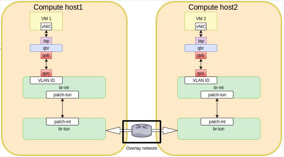
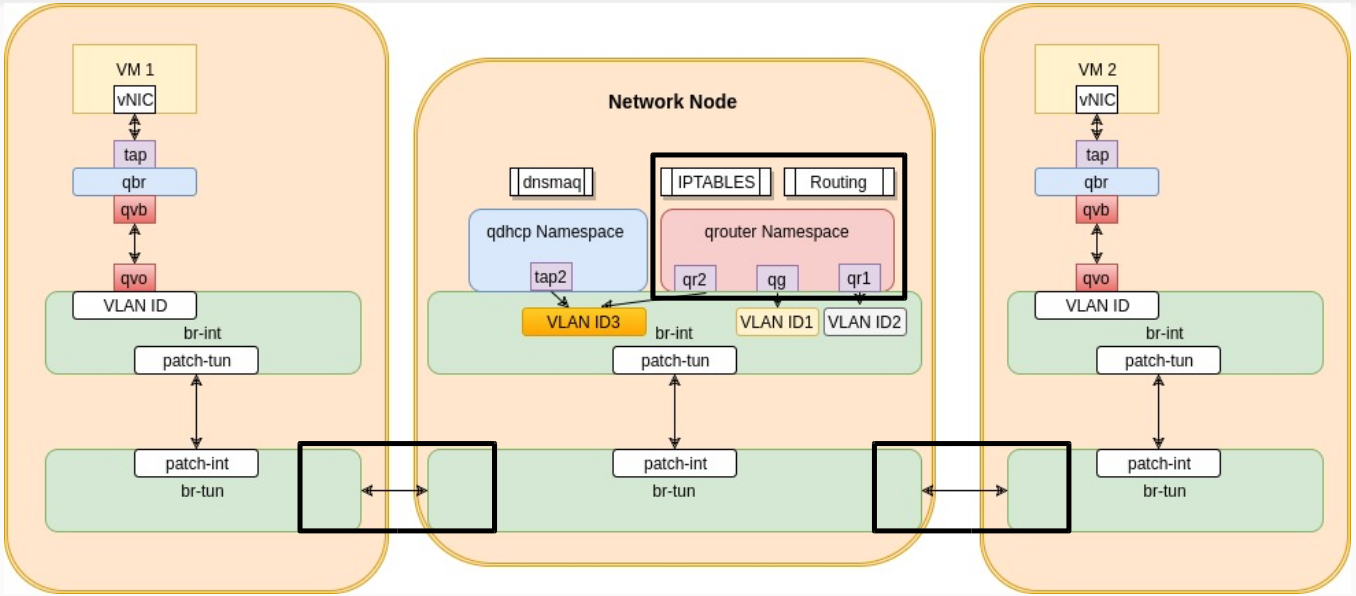
The logical diagram is similar to what we see above. Packets flow from VM1 down through the tap, qbr, qvb-qvo, br-int and br-tun. This time though they have to go through routing before reaching VM2. Routing is done in the router namespaces created by the l3-agent on the network node. In order to see it in more details, let’s look at a more realistic diagram of the communication

As you can see in the diagram above, packets flow through the br-tun from the first compute host to the network node. The network node has a very similar logical diagram as the compute node. It has a br-tun & br-int combination to allow it to establish tunnels to the compute hosts and network hosts in the environment and to VLAN tag local traffic. It has some new entities though which are the qrouter namespace and the qdhcp namespace. From their names it’s obvious they are responsible for routing and dhcp.
Traffic from VM1 reaches the br-tun on the network node on its dedicated tunnel (remember dedicated tunnel ID per network ). br-tun at the network node does the VXLAN tunnel ID to VLAN mapping and pushes the traffic up to the br-int on the network node. The br-int pushes the traffic to the router namespace named qrouter-uuid. This traffic received by the qruoter namespace is router and then pushed down again through the br-int and br-tun. This time it leaves the network node over a VXLAN dedicated tunnel ID, which is different from the VM1 tunnel ID (remember different networks so different tunnel ID). The packets are received by the br-tun of the VM2’s compute host and then goes up through br-int the same way till it reaches VM2
The only case where the tunnel IDs are the same is: If the router is connected to two subnets within the SAME network.
Let’s look more into how qrouter namespace is designed
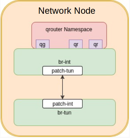
The qrouter namespace has two kinds of interfaces.
- qr interfaces: Those are interfaces that connect the qrouter to the subnets that it is routing between
- qg interface: This is the interface that connects the qrouter to the router’s gateway
If we are assuming a single subnet per network. We can then simplify the qrouter namespace diagram as follows
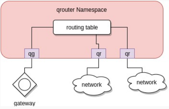
As you can see above , traffic arrives from a certain network on the qr interface. It gets to the routing table of the qrouter namespace and then either goes to the other qr interface if it’s destined to the other network or to the qg interface if it’s destined to the gateway (for example reaching the public network)
Let’s look at a practical scenario, two VMs connected to two different networks.
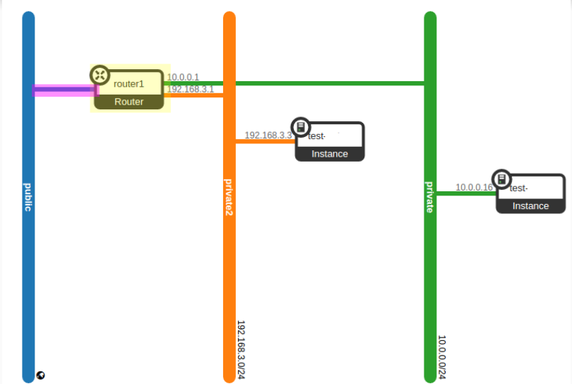
A qrouter namespace physically looks like this on the network node.

If we look inside the qrouter namespace we can see the qr and qg interfaces
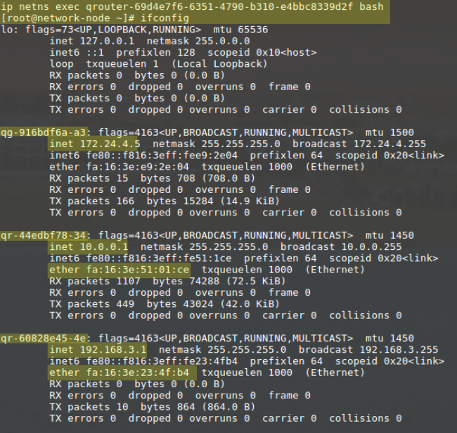
qr interfaces are assigned the ips for the gateways of each network connected and if we look inside the qrouter name space routing table we will see that the qg interface is the default gateway device and that each qr interface is the gatway for the network it’s connected to

A couple of things to remember
- qrouter namespaces are only created when subnets are attached to routers , not when routers are created. i.e. an empty router (no connections to gateway of networks) will have no namespace on the network nodes
- qrouter namespaces are created by the l3-agent
- Although there are more than one qr interface in the qruoter namespace, there’s only one qg interface. This is because the router will have one gateway
- the network node will have as many qrouter namespaces as routers you have for your tenants. The traffic flowing those routers is totally isolated via (VXLAN Tunnel ID, VLAN tag, network namespaces combination)
In the next post we will explain the dhcp address acquiring process of a VM

Hi Mohamed,
Thanks for sharing such a good and detailed traffic flows for different traffic scenarios in Openstack.
Could you please also share the flow for the scenario when both VM’s are in different projects/tenants and want to communicate each other via public IP.
It would be really great full if you can assist me in understanding the said scenario as well.
Thanks once again for sharing your experience and knowledge with us.
Hi Jasdeep,
I am glad they are useful to you. For the scenario you mentioned, the traffic from the VMs will have to “exit” the virtual routers (via qg interfaces), then reach the gateways specified for the routers and then make its way back to the other VM. In other words it will look like this
Scenario:
VM1 -> Tenant 1
VM2 -> Tenant 2
VM1 will generate traffic destined for the public interface of VM2.
Steps for Traffic:
– VM1 traffic exits its compute host towards its VM1 tenant router namespace on the network node
– qg interface in the VM1 tenant router namespace will forward the traffic to its default gw ( you can find this via route -n inside the namespace)
– Traffic hits the gw (in many cases, physical router)
– gw consults its routing table and pushes the traffic back on the same interface ( if they belong to the same public network), but this time destined to VM2 tenant router namespace
– VM2 tenant router namespace receives the traffic on qg interface
– VM2 tenant router namespace forwards the traffic to the compute host of VM2
Great !!